- Set the air pressure, stagger and place the car at ride height.
- Adjust the caster and camber.
- Match your tie rod lengths per the 1-2-3 instructions below and set the toe.
- Center the steering by centering the inner tie rod ends with the Lower Control Arm inner pivot per the 1-2-3 instructions. Lock the steering in place.
- Record a reference point while your car is on the ground and at your design ride height. Measure from the floor to the lower grease fitting or other repeatable spot such as the sway bar mount on the lower control arm – remember to write the number down.
- Place the car on jack stands matching your ride heights and accounting for the jack stand height. The goal is to maintain your ride height suspension angles while on jack stands.
- Bolt on the Bump Steer plate to the hub and set it to level. Jack the suspension to ride height. Lean the JOES Bump Steer Gauge against the hub plate with enough angle so that gravity holds it in place. Set the cross bar parallel to the ground and make sure the legs are parallel. Adjust the roller arm approximately 90 degrees to the cross bar. Match the dial indicator to the roller arm angle so they are both in the same plane.
- Adjust the Bump Steer Gauge cross bar aligning the dial indicator pointer on the zero mark. If you set the cross bar so the dial indicator pointer is on zero you can quickly return to ride height for quick repeat measuring – it will take several tries to get the bump dialed in. The digital dial indicator will display the total amount of bump steer.
- Jack the suspension through travel and write down the bump reading at 1″, 2″ and 3″ (if possible) of travel in both compression and extension with ride height as your starting point.
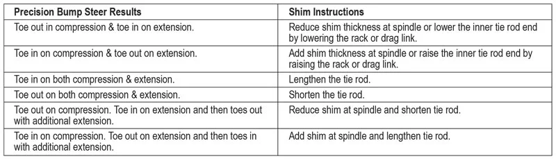
- Shim as needed – the Quick Shim Guide will help to speed the process.
1-2-3 of Zero Bump
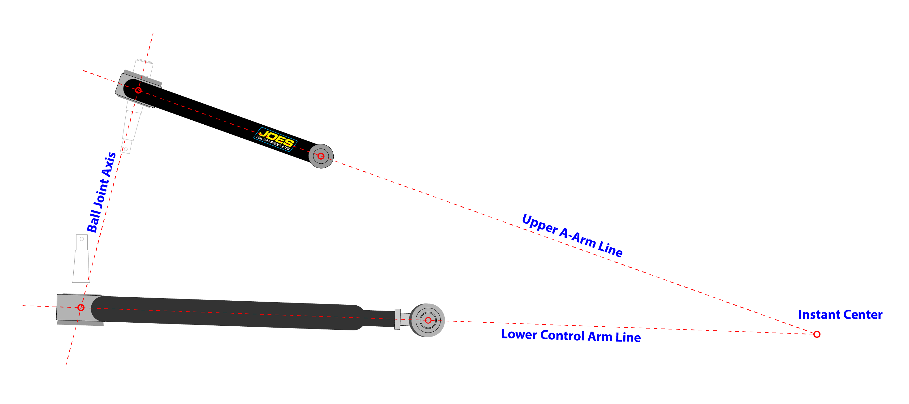
- Your outer tie rod pivot must fall on a line drawn through the upper and lower ball joints.
- Your inner tie rod pivot must fall on a line that is drawn through the Upper A-Arm pivot and Lower Control Arm pivot.
- The angle of the tie rod must create a line that when extended intersects with the Instant Center.
For more information on these principles please refer to our article “Bump Steer & Bump Stops”
Quick Shim Guide