Rolling through the center of the turn at maximum speed requires a suspension that is free of flex yet moves smoothly with out binding. A-arms have improved dramatically and choosing the correct A-arm will help you to create suspension systems that are faster and more consistent.
There are many things to consider when selecting the A-arm for your car. For dirt cars many racers have utilized arms that split at the bolt in ball joint allowing the a-arm to be opened for installations where the A-arm wraps around the frame mount. The split causes additional flex and high quality versions should be considered. The split A-arm utilizes a bolt in ball joint. Many top teams are switching to low friction screw in ball joints for better performance.
Buying an A-arm shaft with simple drilled holes is a less expensive option yet using an A-arm with slots gives you repeatable adjustability. Successful teams keep an inventory of A-arm slugs on hand and pre-measure the caster at each increment in the shop. Pre-measuring lets teams experiment at the track with the confidence that the caster readings will be spot on. Utilizing the slugs creates a precision locating method helping to dial in the set up with quick caster changes right at the track.
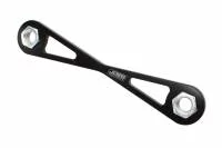
Billet A-Arm Spacers
![]() Billet A-arm spacers help to maintain your settings when making changes at the track. These tapered shims keep your A-arm shaft straight preventing binds.
Billet A-arm spacers help to maintain your settings when making changes at the track. These tapered shims keep your A-arm shaft straight preventing binds.
Machined A-arm spacers have replaced the days of caster camber washers falling all over the ground. A-arm spacers can be purchased in straight or tapered styles helping to keep A-arm shafts straight eliminating binding.
A-Arm Nut Plate
 To further speed the job many teams use a A-arm nut plate that holds the backing nuts allowing use of one ratchet on the front side. Crew members appreciate avoiding the hot headers while holding an end wrench at an awkward angle.
Beyond choosing a slotted version or the basic single hole version, special attention should be paid to the tolerances between the steel A-arm and the shaft. The tolerance is critical as not enough clearance leads to binding and galling. Too much clearance creates unwanted movement and caster change especially under braking. At times excessive clearance can lead to chattering and an unstable car. In dirt applications too much clearance can allow dirt to crawl between the housing and the shaft and the grinding action causes premature wear, sticking and increased friction. Quality A-arm manufactures hold the tolerance for optimal performance.
4 Bearings Spread Out the Load
 4 Bearings spread out the load and this version has a machined bearing housing to keep the shaft in perfect alignment for lower friction.
As the suspension rolls and rides over bumps the A-arm is worked up and down continuously. For more consistent performance many teams are going to bearing style A-arms to eliminate friction. Teams are finding that with roller bearing A-arms that they can sometimes run slightly less spring rate due to the reduced friction. A-arms last longer as the bearings prevent the wear created by the steel A-arm tube contacting the shaft. Heat expansion from the headers and brakes can negatively affect standard A-arms if manufacturers do not use proper clearance. Bearing A-arms effectively eliminate the heat issue.
Bearing Style A-Arms Reduce Friction
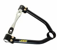 Bearing Style A-arms reduce friction for smooth roll and repeatable performance on the track. This version has a machined bearing housing allowing racers to replace just the steel tube section for quick adjustments or crash repair.
The smooth action of the bearings builds consistent suspension roll and increased corner speed is obtained over a long green flag run. The tight tolerance and low friction of bearing style A-arms eliminates variables allowing crew chiefs to make chassis adjustments with the assurance that the suspension is rolling up and down in a repeatable free flowing fashion. Removing the binding found in less expensive A-arms creates speed as the adjustment decisions are not chasing inconsistencies. Each crew chief decision becomes more effective and every racer should strive to eliminate variables for consistent speed week in and week out. Quality A-arms are powder coated for a premium finish where as less expensive models are spray painted which quickly wears off.
Adjusting the car with A-arm length can be very successful. Shorter RF A-arms create more camber gain and might help you to improve your tire sheet readings. Shortening the RF A-arm moves the front roll center up and to the right. At times the quicker reaction of the RF suspension, due to a shorter A-arm, can improve lap times. Experimenting at your track with A-arm length is just as effective as making a spring change. New A-arms on the market allow you to change the steel A-arm tube section while leaving the shaft bolted to the frame. These new designs speed trackside changes and reduce costs as racers can carry different A-arm tube sections without the added expense of extra shafts.
Big Bar Set Ups generally use longer A-arms than conventional set ups. Camber gain adjustments that line up with your Big Bar Set Up is a critical piece to the puzzle. At times teams jump between a conventional set up and a big bar set up. The A-arms with a bolt on section speeds the A-arm changes that are needed.
Utilizing low friction ball joints with your bearing style A-arm further enhances free movement of the front suspension. Some low friction upper ball joints are adjustable giving racers another adjustment. Fine tuning A-arm angle with the upper ball joint allows for quick roll center adjustments and easy experimentation. Adjustable upper ball joints can be used in conjunction with slotted frame A-Plates. Slotted A-plates allow the inner pivot of the A-arm to be moved up and down and slugs secure the inner pivot in place. The A-Plate slugs are manufactured for precision adjustment in the up/down axis offering another roll center tuning tool.
Without a Proper Weld Bead Flex and Cracking can Occur
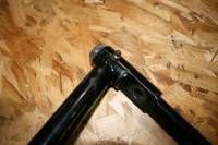 The weld on this A-arm is suspect. With out a proper weld bead flex and cracking can occur. High quality A-arms use thick wall .095 tubing and are TIG Welded.
Some A-arms flex more than most race teams think. Prominent teams test the flex of new A-arm brands before they end up on their car. Manufactures that use thick wall .095 tubing know the slightly more expensive tubing reduces flex as compared to .083 which is commonly used. TIG welding is another feature that will reduce flex. Poor quality wire feed welds make for limp noodles verses a rigid A-arm system. Be sure to inspect the weld quality before purchasing A-arms for your rocket.
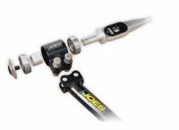
Testing
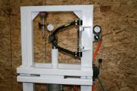 We built this fixture for this test which can apply from 0 to 1500 pounds of force right at the ball joint emulating the conditions seen on your car. We can also set up the fixture to cycle A-arms repeatedly for destructive testing.
Shaft type has an effect on flex. Choosing lightweight aluminum for the cross shaft comes at a price – aluminum flexes more than steel and racers should consider if the few ounces of saved weight in an aluminum cross shaft is a good trade. Our test results show that the steel shaft attached to a 9.5” A-arm flexes .110” at 600 pounds of force where as the aluminum shaft flexes .150” at the same force.
Custom Flex Testing Fixture
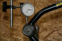 For this test we used our custom flex testing fixture applying force ranging from 200 lbs to 750 lbs. The dial indicator illustrates the flex difference between top brand A-arms and less expensive imitations.
A-ARM Flex Chart
- 9- ½” Bearing Steel Shaft No Name Brand
Flex at 200lbs = .060, at 400 lbs = .100”, at 600 lbs = .135”, at 750 lbs = .155” - 9- ½” Bearing Steel Shaft Quality Brand
Flex at 200lbs = .040, at 400 lbs = .075”, at 600 lbs = .110”, at 750 lbs = .130” - 9- ½” Bearing Aluminum Shaft Quality Brand
Flex at 200lbs = .056, at 400 lbs = .105”, at 600 lbs = .160”, at 750 lbs = .200” - 9- ½” Alum. Shaft (no slot) Quality Brand
Flex at 200lbs = .056, at 400 lbs = .105”, at 600 lbs = .160”, at 750 lbs = .200” - 9- ½” Steel Shaft (no slot) Quality Brand
Flex at 200lbs = .050, at 400 lbs = .075”, at 600 lbs = .110”, at 750 lbs = .130” - 9- ½” Steel Shaft (no slot) No Name Brand
Flex at 200lbs = .090, at 400 lbs = .125”, at 600 lbs = .185”, at 750 lbs = .225”
Our fixture for this test was designed to apply varying pounds of force. The flex chart shows the movement associated with applying lateral pressure at the ball joint center line. The fixture is rigid and the frame mount is the same as you would see on your car. The goal in building the fixture was to emulate what your A-arms see in your racer.
Teams that reduce friction and flex will take another step forward. Racing continues to evolve and teams demand better pieces to find speed. Luckily manufactures are stepping up to the challenge.