Under maximum corner load, where races are won, excessive Bump Steer can slow your car down and make it more difficult to find the optimal set up. Understanding Bump Steer will increase corner speed and give you more options in finding the winning set up.
What is Bump Steer? Bump steer is the toe in and toe out of your front wheels created by the up and down movement of your suspension. Really – bumps aren’t even needed! When the nose lifts under acceleration do you want the wheels to turn in or out on their own? What about when you are under heavy braking? Do you need the Right Front wheel to go one way and the left the other? Think about when the car transitions between compression and extension – we want the driver to steer and not have to correct for the inconsistencies caused by improper front end settings. When the suspension oscillates over bumps the last thing we want is to have the tires turn themselves due to excessive Bump Steer.
Bump Steer is caused when the swing arc of the suspension is not matched to the swing arc of the tie rod. Different swing arcs of the tie rod and suspension are what causes Bump Steer. To match the arcs you must follow a few simple design principles that were considered by your car builder.
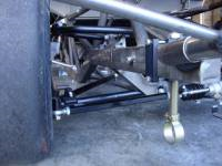
Stock car suspensions are comprised of an Upper A-arm and a Lower Control Arm. Your frame sets the inner pivots and your spindle and ball joints set the outer pivots. Your car builder thought long and hard about all of layout dynamics to engineer the hardware that allows you to properly position components to attain Zero Bump Steer (Fig 1).
(Fig.1) Carefully engineered pivot points, angles and lengths
 (Fig.1) Your car builder carefully engineered the pivot points, angles and lengths. Setting the Bump Steer is like Blue Printing the suspension to exactly match the design specifications.
The layout, lengths, and angles of the upper A-Arm work together with Lower Control Arm to encompass what engineers refer to as an Instant Center. To help understand the Instant Center you can visualize a triangle (Fig. 2). Draw a line from the center pivot of the top ball joint down to the center pivot of the lower ball joint. Now draw a line from the center of the top ball joint through the inner A-Arm pivot and extend it towards the middle of the car. Complete the triangle by drawing a line from the center of the lower ball joint through the inner pivot of the Lower Control Arm and extend it to the spot where it meets the Upper A-Arm line. The intersect point of the two lines is the Instant Center of your suspension. The RF and LF have independent Instant Centers.
(Fig.2) Your pivot points work together and intersect at the Instant Center
(Fig.2) Your pivot points work together and intersect at the Instant Center. The illustration shows the RF suspension from the front view.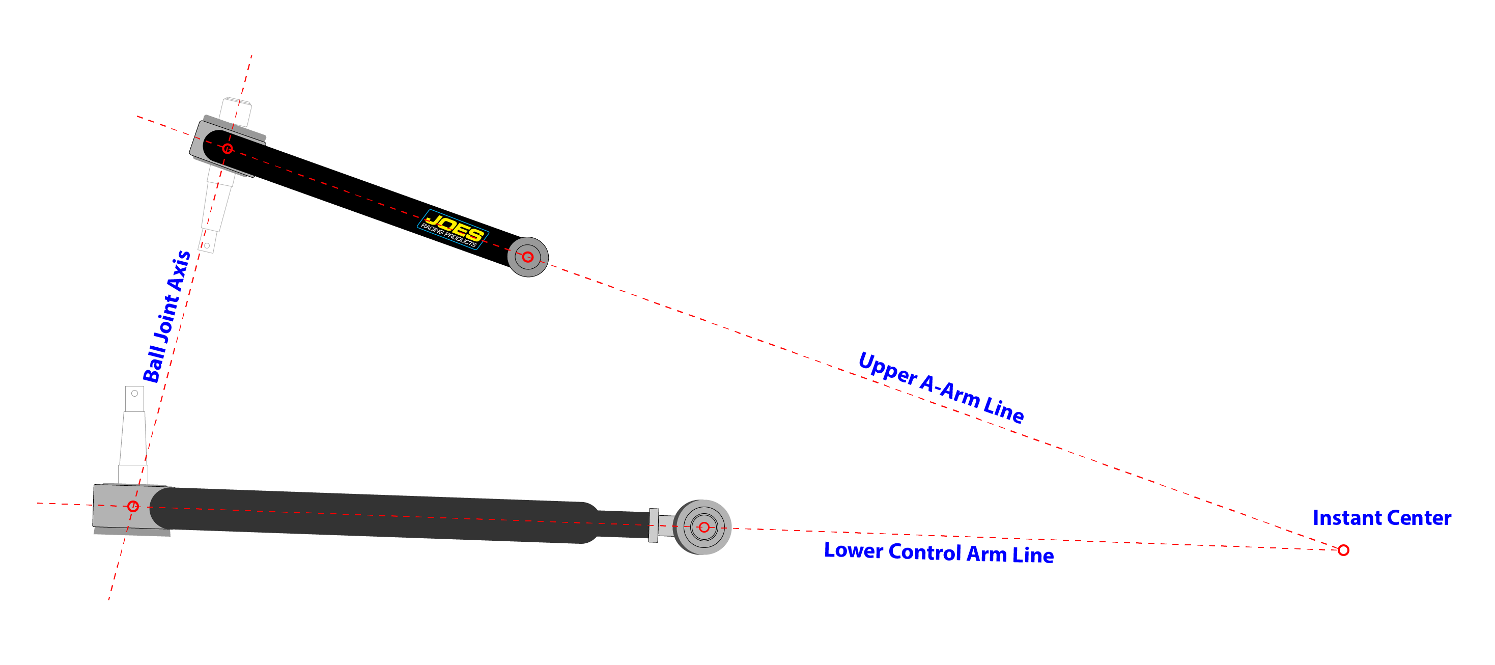
With your triangle drawing (Fig 2.) you can imagine a very long tie rod – one so long it would not fit on a late model as we know it. Connect your imaginary long tie rod with a mental bolt at the Instant Center. Extend your imaginary tie rod out towards the spindle and connect it to the center of the line between the upper and lower ball joint. With this layout you can see that the imaginary tie rod would follow the same arc through travel as the suspension (upper and lower control arms) and the car would achieve zero Bump Steer.
Matching the arc of your actual suspension to the arc of the tie rod completes a design scenario that points your tires straight ahead through suspension movement. To apply the matching arc concept to the design of your late model you will need to consider three design principles for ZERO BUMP.
- Your outer tie rod pivot must fall on a line drawn through the upper and lower ball joints.
- Your inner tie rod pivot must fall on a line that is drawn through the Upper A-Arm pivot and Lower Control Arm pivot.
- The angle of the tie rod must create a line that when extended intersects with the Instant Center.
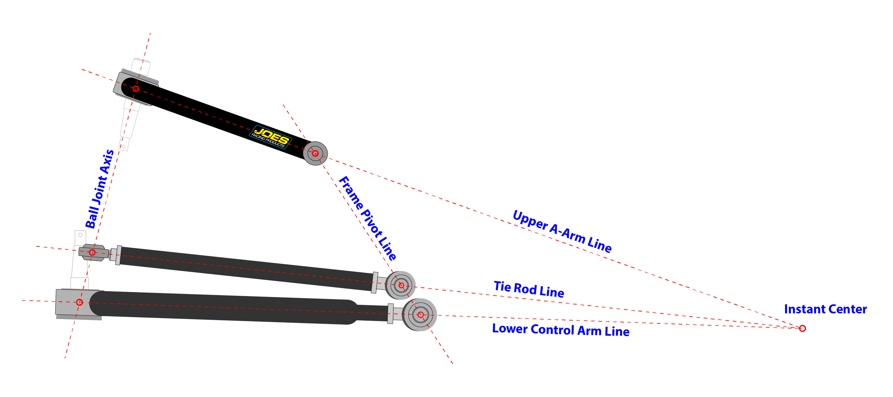
Race cars are made from welded steel that bows and twists from the heat of welding. Rack plates, steering box mounts and spindles all can have variations that we need to account for by utilizing shims to locate the pivots considering our 1-2-3 design elements. Setting the Bump Steer is like blue printing an engine – you are simply going the extra mile to match your car exactly to the car builder design specifications (Fig 3.).
(Fig.3) Typically Stock Car tie rods follow the Lower Control Arm line
(Fig 3.) Typically Stock Car tie rods follow the Lower Control Arm line. In our drawing we are illustrating that you can mount the tie rod elsewhere as long as the outer tie rod end falls on the Ball Joint Axis line, the inner tie rod end falls on the Upper A-arm and Lower Control Arm pivot line – and the angle of the tie rod ends intersect with the Instant Center.
 Often rack plates are mounted too low for direct mounting of the rack. To achieve the proper pivot points detailed in our 1-2-3 instructions we may need to space the rack up (Fig 4). Using CNC machined billet rack spacers adds to the precision or simple washers can be used if you have the correct thickness on hand. Shims may also be needed on the spindle side to account for caster changes or spindle variations.
(Fig.4) Mounting the rack at the proper height allows for zero Bump Steer
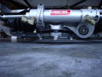 (Fig. 4) Mounting the rack at the proper height allows for zero Bump Steer.
To measure the Bump Steer you need a precision Bump Steer gauge and you will find a digital version speeds up the project. Suspension settings need to be racing ready and the proper components need to be fully installed and tightened. All front end settings need to be set – exactly. Tackling the Bump Steer measuring process should only begin when the car is truly race ready. Prepare your car in the following order and consult your car builder for their recommended front end specs. Make sure you have the right parts on your car!
(Fig.5) A faster and more accurate Bump Steer process
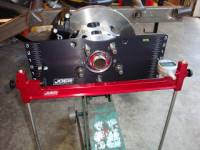 (Fig. 5) A Precision Bump Steer Gauge that is billet rigid and utilizes one dial indicator will do the math for you for a faster and more accurate Bump Steer process.
Prepare the car to measure your Bump Steer per the following Check list:
- Set the tires – air pressures and stagger.
- Set the ride height.
- Adjust the camber.
- Adjust the caster.
- Match your tie rod lengths per the1-2-3 instructions.
- Center the steering by centering the inner tie rod ends with the Lower Control Arm inner pivot per the 1-2-3 instructions. Lock the steering in place to ensure solid measurements.
- Set the toe.
- Record a reference point while your car is on the ground and at your design ride height. Measure from the floor to the lower grease fitting or other repeatable spot such as the sway bar mount on the lower control arm – remember to write the number down.
- Place the car on jack stands matching your ride heights and adjust for the jack stand height. The goal is to maintain your suspension angles while on jack stands matching the ride height on the ground.
- Bolt on the Bump Steer plate to the hub and set it to level. Jack the suspension to ride height and note where the dial indicator touches the Bump Steer plate. Setting Bump Steer is a trial and error process and noting where the dial indicator touches the Bump Steer plate indicator marks will allow you to return to your ride height quickly after attempted adjustments.
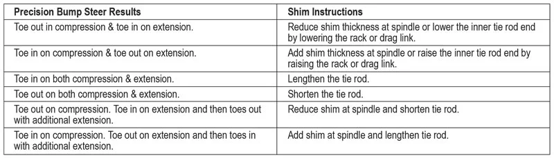
- Jack the suspension fully through compression with bump stop set ups (or at least 2”) and through at least 2” of rebound travel. Write down your results and refer to the Quick Shim Guide (Fig. 6).
- Shim as needed.
(Fig.6) Quick Shim Guide
![]() To help you shim your way to proper Bump Steer here is a Quick Shim Guide that you can use after taking an initial Bump Steer measurement (Fig 6):
To help you shim your way to proper Bump Steer here is a Quick Shim Guide that you can use after taking an initial Bump Steer measurement (Fig 6):
Bump Steer is stated as X amount of Bump Steer (in or out) in 1” of travel. The starting point for measuring Bump Steer is your static ride height. In today’s world of bump stop set ups the reward for zero Bump Steer is even greater. Bump stop set ups allow for more travel – in fact bump stop set ups use all of the travel! More travel multiplies Bump Steer geometry errors and spending the time to get it right does mean more speed and more importantly it produces a fast car all the way to the end. Why fade when you can win? Is improper Bump Steer one of the reasons why some cars slow down at the end of races?
If you have excessive Bump Steer you are un-necessarily heating your tires and wearing them out. The tires go over the bumps in a very fast manner and those millions of in and out toe oscillations generated by too much Bump Steer produces un-wanted tire heat and instability. You can think of it nearly as a toe vibration – in and out – back and forth in rapid motion. Remember, the movements occur through travel not just from bumps. Braking, acceleration, roll, transition all create movements that will magnify Bump Steer. Get rid of Bump Steer and let the driver turn the wheels verses letting the tires turn unpredictably on their own!
So – now that we see the Bump Steer light it is time for the golden question. How much Bump Steer should we run? It’s a matter of opinion and every set up guy has their magic formula. My answer is as close to zero as possible. What ever Bump Steer amount you use should be a recorded and repeatable number that is adjusted verses being an accident. Repeatability in race set up is the way to go.
A small amount of Bump Out is stable. Bump In can cause an unstable car – I always stay away from Bump In. A small amount of Bump Out ensures that my cars avoid Bumping In. A small amount of Bump Out ensures that you avoid Bump In through component flex and it covers unforeseen variations. With Bump Stop Set Ups and Big Bar Soft Spring Set Ups my recommended number is .004 of Bump Out per 1” of travel both left and right.
Before Bump Stop set ups – utilizing a common set up in a 2900 pound touring late model my base Bump Steer set up was .002 to .005 of Bump Out on the RF and .005 to .008 of Bump Out on the LF. Consult your car builder and use his experience. Remember, every car builder has their own idea of Bump Steer settings. Consistency and repeatability are the goal.
“A qualifying trick is to bolt in an extra .187 shim on the LF for your qualifying run which adds about .010 of additional Bump Steer at the LF for a qualifying total of .018 verses my standard .008. Sticker tires and their extra short term grip cover the negative effects of the added Bump for a lap or two. The benefit of the extra Bump Steer is that it manufactures some quick heat in the LF. Under the stress of a one or two lap banzai run the added LF quick heat helps set the car into the middle of the turn – sticker tires make it work”.